CSMA/CA (Carrier-sense multiple access with collision avoidance) is a Layer 1 network multiple access method in which carrier sensing is used, but nodes attempt to avoid collisions by beginning transmission only after the channel is sensed to be "idle". When they transmit, nodes transmit their packet data in its entirety.
CSMA/CD (Carrier sense multiple access with collision detection) is a Layer 1 network multiple access method in which carrier sensing is used, but nodes attempt to avoid collisions by transmitting only when the channel is sensed to be idle. When they transmit, nodes transmit their packet data in its entirety.
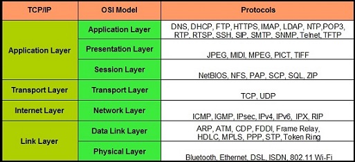
DHCP (Dynamic Host Configuration Protocol) is a Layer 7 network management protocol used on IP networks for automatically addresses and other communication parameters to devices connected to the network using a client–server architecture.
DNS (Domain Name System) is a Layer 7 hierarchical and decentralized naming system used to identify computers, services, and other resources reachable through the Internet or other IP networks.
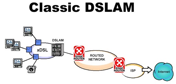
DSL (Digital subscriber line) is a Layer 1 family of technologies that are used to transmit digital data over telephone lines. In telecommunications marketing, the term DSL is widely understood to mean ADSL (asymmetric), the most commonly installed DSL technology, for Internet access. DSL service can be delivered simultaneously with wired telephone service on the same telephone line since DSL uses higher frequency bands for data. On the customer premises, a DSL filter on each non-DSL outlet blocks any high-frequency interference to enable simultaneous use of the voice and DSL services.
Ethernet Is a Layer 1 family of wired computer networking technologies commonly used LAN, MAN and WAN networks. Commercially introduced in 1980 and standardized in 1983 as IEEE 802.3, ethernet has since been refined to support higher bit rates, a greater number of nodes, and longer link distances and retains much backward compatibility. It has largely replaced competing wired LAN technologies (Token Ring, FDDI and ARCNET). Original 10BASE5 Ethernet uses coaxial cable as a shared medium. Newer Ethernet variants use twisted pair and fiber optic links in conjunction with switches. Data transfer rates have increased from 2.94 Mbit/s to 400 Gbit/s Rates up to 1.6 Tbit/s are under development. Ethernet standards include several wiring and signaling variants of the OSI physical layer. Ethernet divides a stream of data into shorter pieces called frames. Each frame contains source and destination addresses, and error-checking data. Often, higher-layer protocols trigger retransmission of lost frames
Frame Relay Is a Layer 1 standardized WAN technology that specifies the physical and data link layers of digital telecommunications channels using a packet switching methodology. Designed for ISDN infrastructure, it may be used today in the context of many other network interfaces. Network providers commonly implement Frame Relay for voice (VoFR) and data as an encapsulation technique used between local area networks (LANs) over a WAN. Each end-user gets a private line (or leased line) to a Frame Relay node. The Frame Relay network handles the transmission over a frequently changing path transparent to all end-user extensively used WAN protocols.
IEEE 802.11 is a Layer 1 and a part of the IEEE 802 set of LAN technical standards, and specifies the set of MAC and PHY protocols for implementing WLAN computer communication. The standard and amendments provide the basis for wireless network products using the Wi-Fi brand and are the world's most widely used wireless computer networking standards. IEEE 802.11 is used in most home and office networks to allow laptops, printers, smartphones, and other devices to communicate with each other and access the Internet without connecting wires.
ICMP (Internet Control Message Protocol) is a Layer 3 supporting protocol in the Internet protocol suite. It is used by network devices, including routers, to send error messages and operational information indicating success or failure when communicating with another IP address.
IGP (Internet Group Management Protocol - IPv4) is a Layer 3 communications protocol used by hosts and adjacent routers to establish multicast group memberships. Allows the network to direct multicast transmissions only to hosts that have requested them.
IMAP (Internet Message Access Protocol) is a Layer 7 Internet standard protocol used by email clients to retrieve email messages from a mail server over a TCP/IP connection.
ISDN (Integrated Services Digital Network) is a Layer 1 set of communication standards for simultaneous digital transmission of voice, video, data, and other network services over the digitalised circuits of the public switched telephone network. Work on the standard began in 1980 at Bell Labs and was formally standardized in 1988 in the CCITT Red Book.
IPv4 (Internet Protocol version 4) is the fourth version of the Internet Protocol IP. It is one of the core protocols of standards-based internetworking methods in the Internet and other packet-switched networks. IPv4 was the first version deployed for production on SATNET in 1982 and on the ARPANET in January 1983.
IPv6 (Internet Protocol version 6) is the most recent version of the Internet Protocol IP, the communications protocol that provides an identification and location system for computers on networks and routes traffic across the Internet. IPv6 was developed by the Internet Engineering Task Force (IETF) to deal with the long-anticipated problem of IPv4 address exhaustion, and is intended to replace IPv4.
IPX (Internetwork Packet Exchange) is a Layer 3 protocol in the IPX/SPX protocol suite. IPX is derived from Xerox Network System IDP. It also has the ability to act as a transport layer protocol.
POP3 (Post Office Protocol) is Layer 7. It provides access via IP for a user client application to a maildrop maintained on a mail server. Supports download and deletion for messages. POP3 clients connect, retrieve all messages, store them on the client computer, and finally delete them from the server.
RIP (Routing Information Protocol) is a Layer 3. It is one of the oldest distance-vector routing protocols which employs the hop count as a routing metric. RIP prevents routing loops by implementing a limit on the number of hops allowed in a path from source to destination. The largest number of hops allowed for RIP is 15, which limits the size of networks that RIP can support. RIP implements the split horizon, route poisoning, and holddown mechanisms to prevent incorrect routing information from being propagated. In RIPv1 routers broadcast updates with their routing table every 30 seconds. In the early deployments, routing tables were small enough that the traffic was not significant. As networks grew in size, however, it became evident there could be a massive traffic burst every 30 seconds, even if the routers had been initialized at random times.
TCP (Transmission Control Protocol) provides reliable, ordered, and error-checked delivery of a stream of octets between applications running on hosts communicating via IP. The World Wide Web, email, remote administration, and file transfer rely on TCP, which is part of the Transport Layer of the TCP/IP suite. SSL/TLS often runs on top of TCP. TCP is connection-oriented, the server must be listening for connection requests from clients before a connection is established. Three-way handshake, retransmission, and error detection adds to reliability but lengthens latency. Applications that do not require reliable data stream service may use UDP.
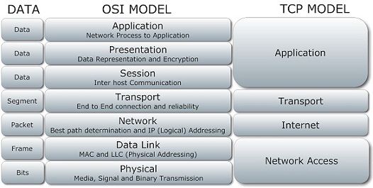
TCP/IP (Internet protocol suite) is a Layer 4 set of communications protocols used in the Internet and similar computer networks. The current foundational protocols in the suite are the Transmission Control Protocol and Internet Protocol. The Internet protocol suite provides end-to-end data communication specifying how data should be packetized, addressed, transmitted, routed, and received.
UDP (User Datagram Protocol) is Layer 4. One of the core members of the Internet protocol suite. With UDP, computer applications can send messages, in this case referred to as datagrams, to other hosts on an IP network. Prior communications are not required in order to set up communication channels or data paths. UDP uses a simple connectionless communication model with a minimum of protocol mechanisms. UDP provides checksums for data integrity and port numbers for addressing different functions at the source and destination of the datagram. It has no handshaking dialogues, thus exposes the user's program to any unreliability of the underlying network There is no guarantee of delivery, ordering, or duplicate protection. If error-correction facilities are needed at the network interface level, an application may instead use TCP or SCTP which are designed for this purpose.
    127   0 1 1 1  1 1 1 1
    128   1 0 0 0  0 0 0 0
    191   1 0 1 1  1 1 1 1
    192   1 1 0 0  0 0 0 0
    223   1 1 0 1  1 1 1 1
    224   1 1 1 0  0 0 0 0
    239   1 1 1 0  1 1 1 1

    Class A        1 - 127
    Class B      128 - 191
    Class C      192 - 223
              Class B

    Bits        Mask       Subnets       Hosts
    1      255.255.128.0         2       32766
    2      255.255.192.0         4       16382
    3      255.255.224.0         8        8190
    4      255.255.240.0        16        4094
    5      255.255.248.0        32        2046
    6      255.255.252.0        64        1022
    7      255.255.254.0       128         510
    8      255.255.255.0       256         254
    9      255.255.255.128     512         126
    10     255.255.255.192    1024          62
    11     255.255.255.224    2048          30
    12     255.255.255.240    4096          14
    13     255.255.255.248    8192           6
    14     255.255.255.252   16384           2

              Class C

    1      255.255.255.128       2         126
    2      255.255.255.192       4          62
    3      255.255.255.224       8          30
    4      255.255.255.240      16          14
    5      255.255.255.248      32           6
    6      255.255.255.252      64           2
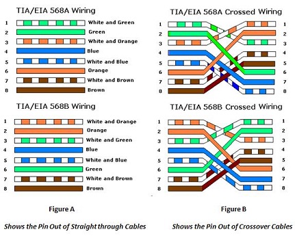
Straight-Through refers to cables that have the pin assignments on each end of the cable. In other words Pin 1 connector A goes to Pin 1 on connector B, Pin 2 to Pin 2 ect. Straight-Through wired cables are most commonly used to connect a host to client. When we talk about cat5e patch cables, the Straight-Through wired cat5e patch cable is used to connect computers, printers and other network client devices to the router switch or hub (the host device in this instance).
    Connector A:      Connector B:
      Pin 1             Pin 1
      Pin 2             Pin 2
      Pin 3             Pin 3
      Pin 4             Pin 4
      Pin 5             Pin 5
      Pin 6             Pin 6
      Pin 7             Pin 7
      Pin 8             Pin 8
Crossover wired cables (commonly called crossover cables) are very much like Straight-Through cables with the exception that TX and RX lines are crossed (they are at oposite positions on either end of the cable. Using the 568-B standard as an example below you will see that Pin 1 on connector A goes to Pin 3 on connector B. Pin 2 on connector A goes to Pin 6 on connector B ect. Crossover cables are most commonly used to connect two hosts directly. Examples would be connecting a computer directly to another computer, connecting a switch directly to another switch, or connecting a router to a router.Note: While in the past when connecting two host devices directly a crossover cable was required. Now days most devices have auto sensing technology that detects the cable and device and crosses pairs when needed.
    Connector A:      Connector B:
      Pin 1             Pin 3
      Pin 2             Pin 6
      Pin 3             Pin 1
      Pin 4             Pin 7
      Pin 5             Pin 8
      Pin 6             Pin 2
      Pin 7             Pin 4
      Pin 8             Pin 5
Rollover wired cables most commonly called rollover cables, have opposite Pin assignments on each end of the cable or in other words it is "rolled over". Pin 1 of connector A would be connected to Pin 8 of connector B. Pin 2 of connector A would be connected to Pin 7 of connector B and so on. Rollover cables, sometimes referred to as Yost cables are most commonly used to connect to a devices console port to make programming changes to the device. Unlike crossover and straight-wired cables, rollover cables are not intended to carry data but instead create an interface with the device.
    Connector A:      Connector B:
      Pin 1             Pin 8
      Pin 2             Pin 7
      Pin 3             Pin 6
      Pin 4             Pin 5
      Pin 5             Pin 4
      Pin 6             Pin 3
      Pin 7             Pin 2
      Pin 8             Pin 1